Note
Go to the end to download the full example code. or to run this example in your browser via Binder
Offset QPSK Modulation
This example demonstrates Offset QPSK (OQPSK) modulation in Kaira. OQPSK is a variant of QPSK where the quadrature component is delayed by half a symbol period relative to the in-phase component.
This delay ensures that only one bit can change at a time, restricting phase changes to 90° and reducing envelope fluctuations, which is beneficial for power-efficient RF amplification.
import matplotlib.pyplot as plt
Imports and Setup
import numpy as np
import torch

from kaira.channels import AWGNChannel
from kaira.metrics.signal import BER
from kaira.modulations import OQPSKDemodulator, OQPSKModulator, QPSKDemodulator, QPSKModulator
from kaira.modulations.utils import plot_constellation
from kaira.utils import snr_to_noise_power

# Set random seed for reproducibility
torch.manual_seed(42)
np.random.seed(42)
Generate Random Binary Data
n_symbols = 1000
bits = torch.randint(0, 2, (1, 2 * n_symbols))  # Each symbol uses 2 bits
print(f"Number of bits: {bits.numel()}")
Number of bits: 2000
Create Modulators and Demodulators
oqpsk_mod = OQPSKModulator()
oqpsk_demod = OQPSKDemodulator()

# Regular QPSK for comparison
qpsk_mod = QPSKModulator()
qpsk_demod = QPSKDemodulator()

# Modulate the data
oqpsk_symbols = oqpsk_mod(bits)
qpsk_symbols = qpsk_mod(bits)
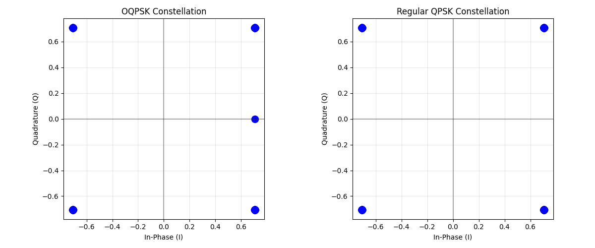
Visualize Constellations
fig, axs = plt.subplots(1, 2, figsize=(12, 5))

# OQPSK constellation
plot_constellation(oqpsk_symbols.flatten(), title="OQPSK Constellation", marker="o", ax=axs[0])
axs[0].grid(True)

# Regular QPSK constellation for comparison
plot_constellation(qpsk_symbols.flatten(), title="Regular QPSK Constellation", marker="o", ax=axs[1])
axs[1].grid(True)

plt.tight_layout()
plt.show()
Visualize Symbol Transitions
Generate a specific bit pattern to demonstrate transitions Using a pattern that would cause diagonal transitions in QPSK
pattern_bits = torch.tensor([[0, 0, 0, 1, 1, 1, 1, 0, 0, 0, 1, 1, 0, 1, 1, 0]])

# Reset modulator states
oqpsk_mod.reset_state()
qpsk_mod.reset_state()

# Modulate the pattern
oqpsk_pattern = oqpsk_mod(pattern_bits)
qpsk_pattern = qpsk_mod(pattern_bits)

# Plot transitions
fig, axs = plt.subplots(1, 2, figsize=(12, 5))

# OQPSK transitions
axs[0].plot(oqpsk_pattern[0].real, oqpsk_pattern[0].imag, "bo-", linewidth=2)
axs[0].plot(oqpsk_pattern[0, 0].real, oqpsk_pattern[0, 0].imag, "ro", markersize=10, label="Start")
axs[0].grid(True)
axs[0].set_aspect("equal")
axs[0].set_title("OQPSK Symbol Transitions")
axs[0].set_xlabel("In-phase")
axs[0].set_ylabel("Quadrature")
axs[0].legend()

# QPSK transitions
axs[1].plot(qpsk_pattern[0].real, qpsk_pattern[0].imag, "bo-", linewidth=2)
axs[1].plot(qpsk_pattern[0, 0].real, qpsk_pattern[0, 0].imag, "ro", markersize=10, label="Start")
axs[1].grid(True)
axs[1].set_aspect("equal")
axs[1].set_title("QPSK Symbol Transitions")
axs[1].set_xlabel("In-phase")
axs[1].set_ylabel("Quadrature")
axs[1].legend()

plt.tight_layout()
plt.show()

Visualize Phase and Amplitude Properties
Generate a longer sequence to demonstrate phase changes
long_bits = torch.randint(0, 2, (1, 2 * 200))

# Reset modulator states
oqpsk_mod.reset_state()
qpsk_mod.reset_state()

# Modulate bits
oqpsk_long = oqpsk_mod(long_bits)
qpsk_long = qpsk_mod(long_bits)

# Calculate phase changes between consecutive symbols
oqpsk_phase = torch.angle(oqpsk_long)
qpsk_phase = torch.angle(qpsk_long)

oqpsk_phase_diff = torch.abs(torch.diff(oqpsk_phase, dim=1))
qpsk_phase_diff = torch.abs(torch.diff(qpsk_phase, dim=1))

# Wrap phase differences to [-π, π]
oqpsk_phase_diff = torch.remainder(oqpsk_phase_diff + torch.pi, 2 * torch.pi) - torch.pi
qpsk_phase_diff = torch.remainder(qpsk_phase_diff + torch.pi, 2 * torch.pi) - torch.pi

# Calculate envelopes (magnitude)
oqpsk_envelope = torch.abs(oqpsk_long)
qpsk_envelope = torch.abs(qpsk_long)

# Plot phase differences and envelopes
fig, axs = plt.subplots(2, 2, figsize=(12, 10))

# Phase changes
axs[0, 0].hist(oqpsk_phase_diff[0].numpy(), bins=50, alpha=0.7, label="OQPSK")
axs[0, 0].grid(True)
axs[0, 0].set_title("OQPSK Phase Changes")
axs[0, 0].set_xlabel("Phase change (radians)")
axs[0, 0].set_ylabel("Frequency")

axs[0, 1].hist(qpsk_phase_diff[0].numpy(), bins=50, alpha=0.7, label="QPSK")
axs[0, 1].grid(True)
axs[0, 1].set_title("QPSK Phase Changes")
axs[0, 1].set_xlabel("Phase change (radians)")
axs[0, 1].set_ylabel("Frequency")

# Envelopes
axs[1, 0].plot(oqpsk_envelope[0].numpy(), "b-", linewidth=1.5)
axs[1, 0].grid(True)
axs[1, 0].set_title("OQPSK Envelope")
axs[1, 0].set_xlabel("Symbol index")
axs[1, 0].set_ylabel("Envelope magnitude")
axs[1, 0].set_ylim(0, 1.5)

axs[1, 1].plot(qpsk_envelope[0].numpy(), "r-", linewidth=1.5)
axs[1, 1].grid(True)
axs[1, 1].set_title("QPSK Envelope")
axs[1, 1].set_xlabel("Symbol index")
axs[1, 1].set_ylabel("Envelope magnitude")
axs[1, 1].set_ylim(0, 1.5)

plt.tight_layout()
plt.show()

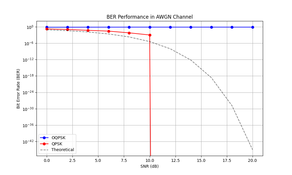
Performance in AWGN Channel
Compare OQPSK with regular QPSK in AWGN
snr_db_range = np.arange(0, 21, 2)
ber_oqpsk = []
ber_qpsk = []

# Initialize BER metric
ber_metric = BER()

# Reset modulator states
oqpsk_mod.reset_state()
oqpsk_demod.reset_state()

for snr_db in snr_db_range:
    # Calculate noise power and create AWGN channel
    noise_power = snr_to_noise_power(1.0, snr_db)
    channel = AWGNChannel(avg_noise_power=noise_power)

    # OQPSK transmission
    received_oqpsk = channel(oqpsk_symbols)
    demod_bits_oqpsk = oqpsk_demod(received_oqpsk)
    ber_oqpsk.append(ber_metric(demod_bits_oqpsk, bits).item())

    # QPSK transmission
    received_qpsk = channel(qpsk_symbols)
    demod_bits_qpsk = qpsk_demod(received_qpsk)
    ber_qpsk.append(ber_metric(demod_bits_qpsk, bits).item())

# Plot BER vs SNR
plt.figure(figsize=(10, 6))
plt.semilogy(snr_db_range, ber_oqpsk, "bo-", label="OQPSK")
plt.semilogy(snr_db_range, ber_qpsk, "ro-", label="QPSK")

# Theoretical QPSK BER
snr_lin = 10 ** (snr_db_range / 10)
theoretical_ber = torch.erfc(torch.sqrt(torch.tensor(snr_lin))) / 2
plt.semilogy(snr_db_range, theoretical_ber, "k--", alpha=0.5, label="Theoretical")

plt.grid(True)
plt.xlabel("SNR (dB)")
plt.ylabel("Bit Error Rate (BER)")
plt.title("BER Performance in AWGN Channel")
plt.legend()
plt.show()
Effect of Noise on Constellation
Let’s visualize how noise affects the constellation diagrams
test_snr_db = 10  # 10 dB SNR
noise_power = snr_to_noise_power(1.0, test_snr_db)
channel = AWGNChannel(avg_noise_power=noise_power)

# Generate new random data
test_bits = torch.randint(0, 2, (1, 2 * 500))

# Reset modulator states
oqpsk_mod.reset_state()
qpsk_mod.reset_state()

# Modulate and transmit through channel
oqpsk_test = oqpsk_mod(test_bits)
qpsk_test = qpsk_mod(test_bits)

received_oqpsk = channel(oqpsk_test)
received_qpsk = channel(qpsk_test)

# Plot noisy constellations
fig, axs = plt.subplots(1, 2, figsize=(12, 5))

plot_constellation(received_oqpsk.flatten(), title=f"OQPSK at {test_snr_db} dB SNR", marker=".", ax=axs[0])
axs[0].grid(True)

plot_constellation(received_qpsk.flatten(), title=f"QPSK at {test_snr_db} dB SNR", marker=".", ax=axs[1])
axs[1].grid(True)

plt.tight_layout()
plt.show()

Conclusion
This example demonstrated:
Implementation of OQPSK modulation using Kaira
Visualization of constellation diagrams and symbol transitions
Comparison of phase changes and envelope properties with QPSK
BER performance analysis in AWGN channels
Key observations:
OQPSK looks identical to QPSK in the constellation diagram but behaves differently over time
In OQPSK, phase changes are restricted to 0° or ±90° (no 180° phase reversals)
This results in more stable envelope characteristics compared to QPSK
Both schemes achieve similar BER performance in AWGN
The half-symbol delay in OQPSK’s quadrature component prevents the signal from crossing through the origin, which is beneficial for systems using non-linear amplifiers
Total running time of the script: (0 minutes 1.208 seconds)